Robot Arm V2: Electronics
- 3 minsThings have been busy, but I am trying to make more time for this project! This post is an update on some of the electronics and software for the Arm.
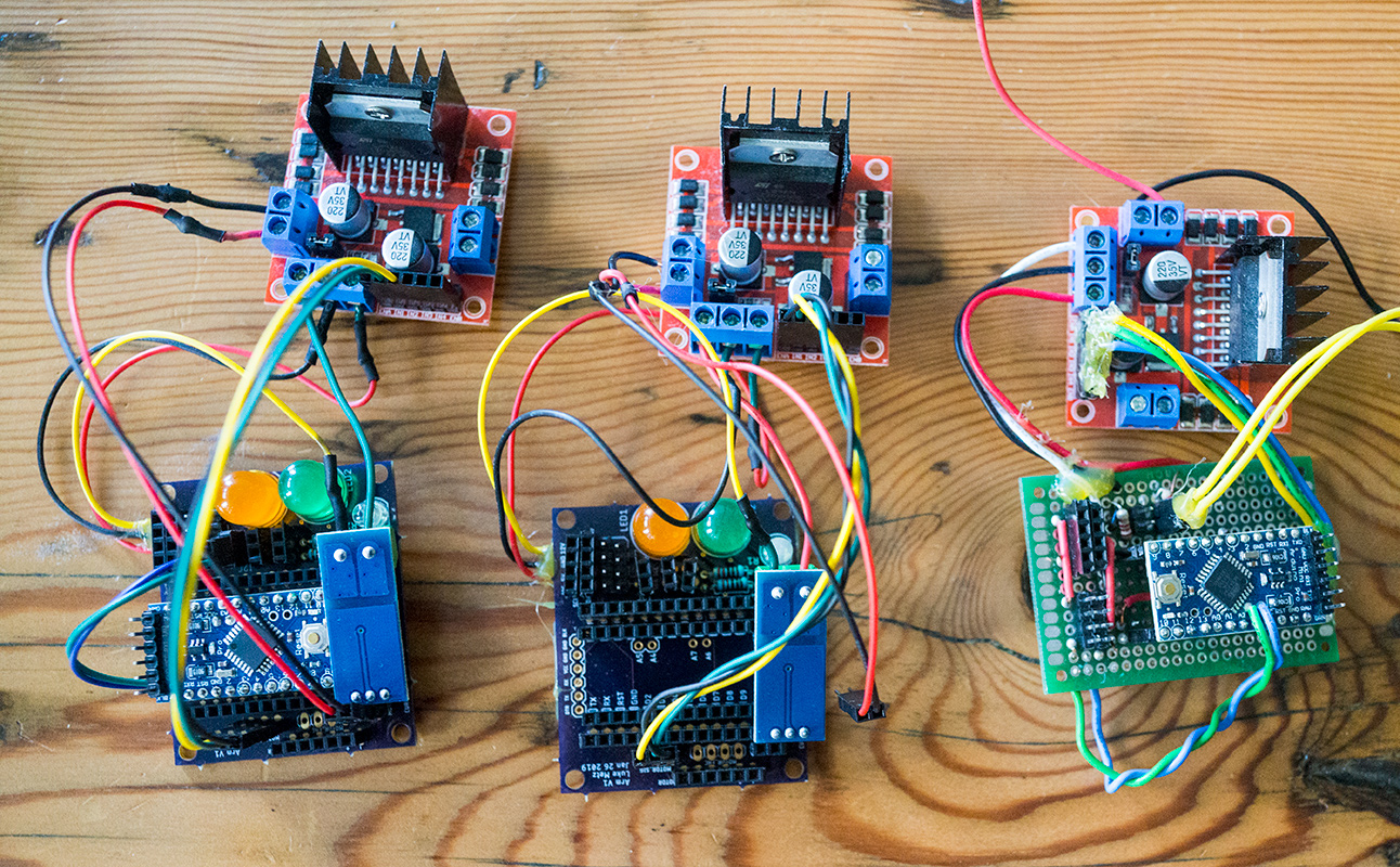
In terms of electronics, the previous design consisted of one base microcontroller that controlled everything with wires directly going to each motor. This was not scalable, not modular, and led to too many wires everywhere. Additionally, given the new slip ring, I did not have enough high current channels to make this approach possible. As such, I opted to be more distributed. I still have one base controller, connected to a PC for commands, but this controller is connected to a I2C bus. I2C is a simple, synchronous, master slave protocol that comes built in to many sensors and microcontrollers. For each axis, I have another microcontroller that converts the incoming commands to drive motors, as well as potentially manages and sends back encoder data. Each board is daisy chained together with an 8 channel connector, with 2 channels for I2C, each with 2x for +12V, +5V, and GND.
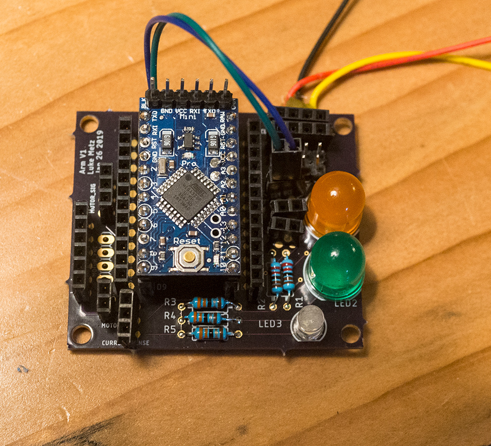
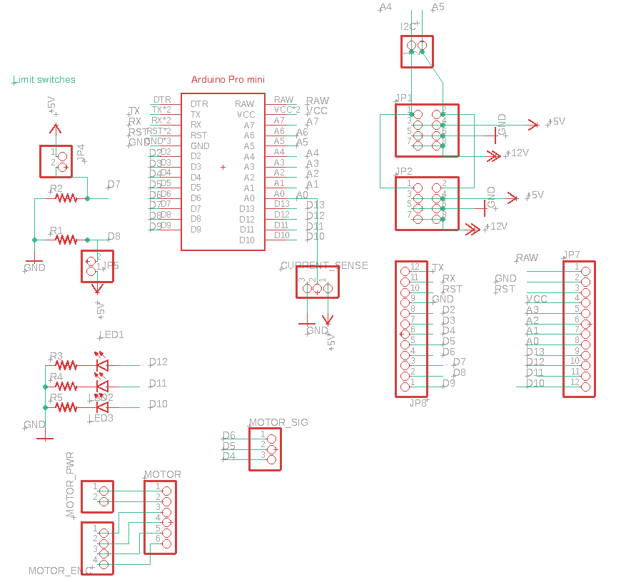
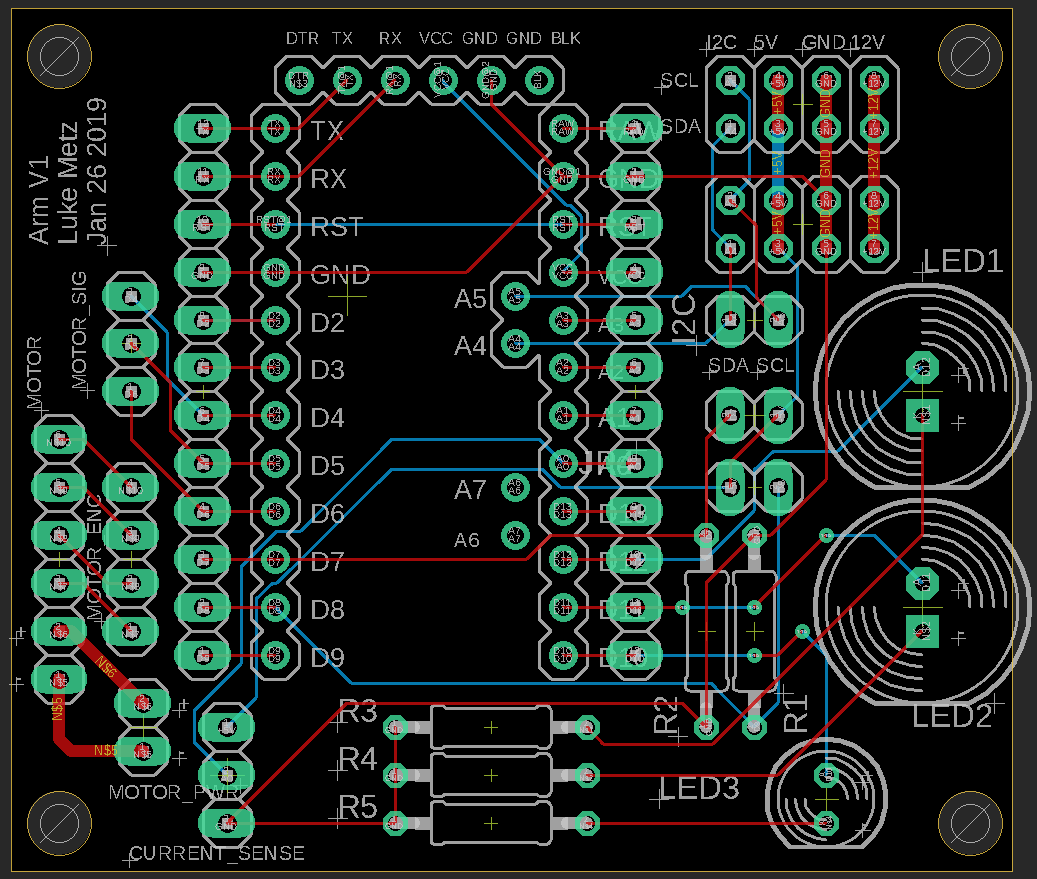
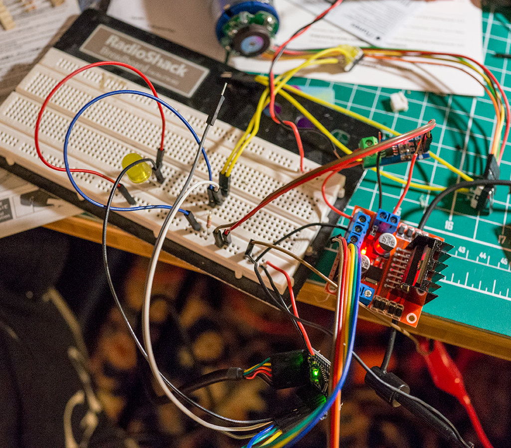
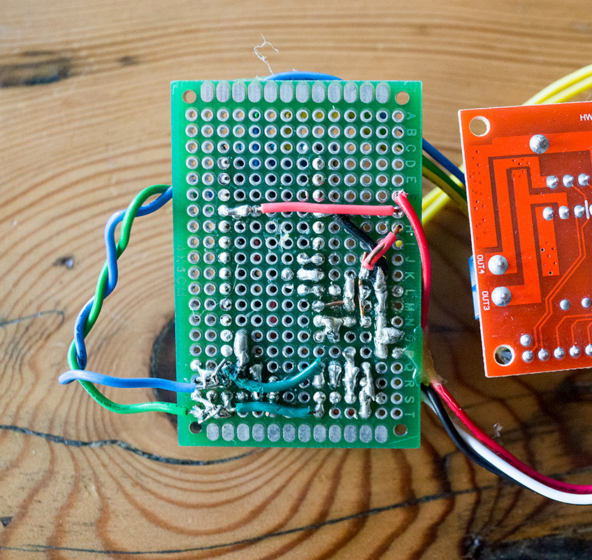
I realized early in the last iteration that breadboard based electronics were not going to cut it. Too many wires, and too hard to debug if something came loose. That, and I am to lazy to cut wires to the correct lengths. Perfboards are better. I tried to work with these, but concluded that soldering and working with them was time consuming and not very fun. After building one board, I gave up and decided to dive into the world of custom PCB! I learned, and made schematics in Eagle, and sent them to oshpark for fabrication. Turnaround time was < 1 week which is amazing – would highly recommend this process! The circuits themselves are simple – really just an Arduino shield, some connectors, a few resistors, and some LED for debugging. For simplicity, I chose not to place the circuit for the motor driver, nor the Arduino, on my boards. I didn’t want to source components, am not equipped to do the required volume of surface mount soldering, and am not all that confident with so much electrical engineering. As a result, the full electronics are a bit messy, requiring many connections between the motor controller and the Arduino board. Next iteration, I plan on reconsidering this, as I spent the majority of the time making connectors.
On the software side, I am still sending inputs from an Xbox controller over sending SLIP to the master board. The master board now sends packets over I2C to each slave board. The slave boards listen for these, then set the appropriate pins to control the motor controller.
As of now, I have 2 axis more or less assembled with electronics. Current plans now are to 3D print and assemble a third axis, finish up controls, get more sensor data out, and figure out how to control this thing!