Robot Arm Mechanical Design V2: Base
- 7 minsIt’s time for another iteration on the mechanical side of things. The old design had a number of issues. Foremost, at 20 kg-cm torque, the motors were incredibly underpowered. As a result, the base joint could not lift the remaining joints. Secondly, the lack of cable management on the old design meant that the base was not free to rotate fully without tangling. In addition, the use of spur gears meant that there was a lot of play / backlash in the whole system. Finally, assembly was a pain – the old design took far too long to put together. As such, I have been busy designing this last month, and have just now started to print some of the resulting pieces. This post will give an overview of the newly designed first axis!
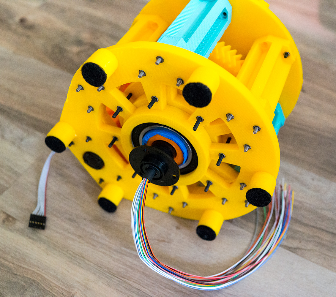
Slip Ring
To manage wiring, I decided to try to make use of a slip ring. Slip rings are devices that enable electrical power transfer through rotation. Sadly, I couldn’t seem to find exactly what I wanted – a low diameter, high current ring that was not a fortune. I ended up going with this one with the expectation that I will solder many of the wires together to increase power transfer. It is not small in diameter though, and to be effective the wire must be at the center of rotation. As such, I was in need of an essentially hollow shaft.
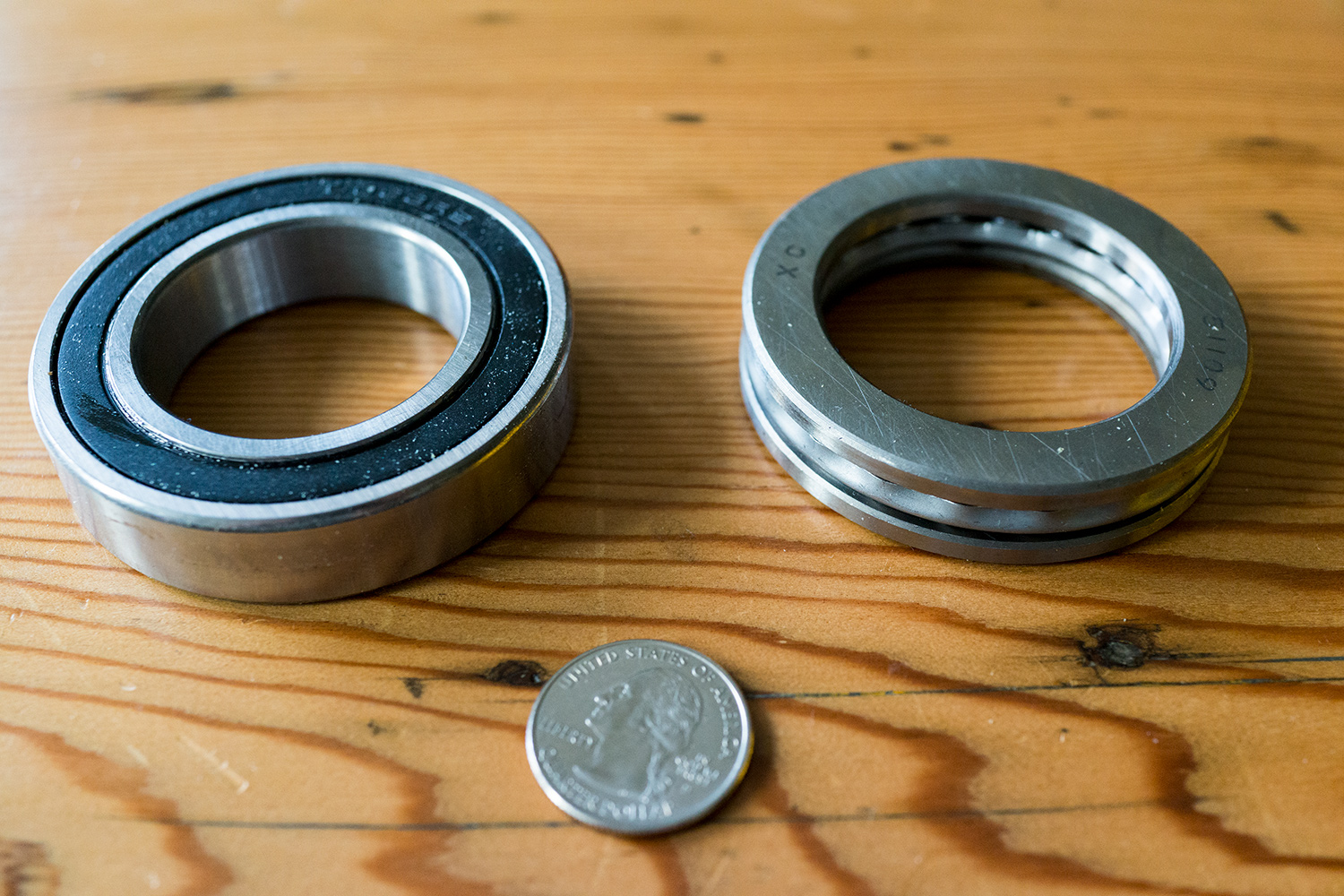
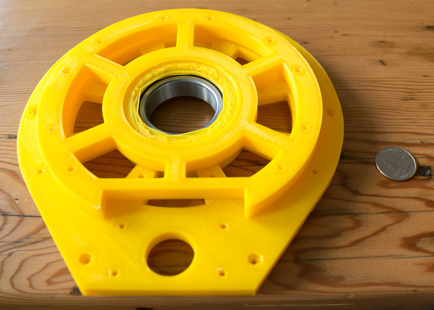
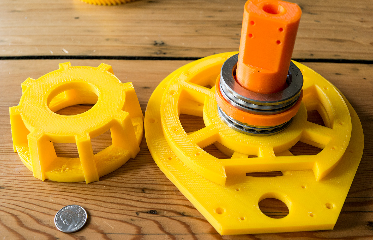
Hollow 3D Printed Shaft
Inspired by Ttanaka’s arm and the Thor arm, I decided to try the to make use of 3D printed axles / shafts. To fit around the slip ring, the inner diameter of this axel needs to be ~22 mm, which is quite large. Because of this size, I ended up using massive bearings to hold everything in place. For axial load I am using 51109 thrust bearings. To keep the shaft aligned, I am using 6008 deep groove ball bearings. Both of these are massively overkill in their max specs, but they fit the sizes that I need. I was debating to use just the 6008 for both axial and off axial load, but was unsure if the 3D printed parts would be strong enough as they would only be able to contact the race of the bearing (a few mm in diameter ring).
The actual bearing assembly is quite similar to the design from my first post. I sandwiched a 3D printed part between 2 thrust bearings, and then clamped the other ends of the thrust bearings together.
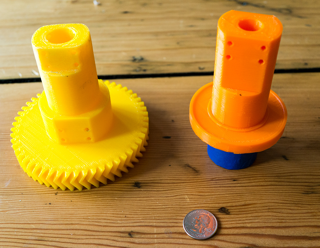
Herringbone Gears
For gears, I swapped out the original spur gears with herringbone gears. These gears have much smoother motion as compared to spur gears, which results in less backlash. One of my favorite features about OnShape, the CAD program I am using, is FeatureScript. It exposes a programming language to design custom features or use other people’s. So instead of painstakingly cadding these gears, I used Aaron Griffith’s wonderful FeatureScript feature to create these gears! I have been using FeatureScript as much as I can in this project and plan to write a post specifically on this language in the future!
I had a lot of difficulty thinking about how to attach this gear to the shaft while keeping the diameter small enough to fit the bearings. My final solution ended up solving the problem by making the entire shaft 2 pieces and 3D printing the gear with the second half of shaft! This ended up being quite strong and is easy to assemble.
New Motors
Instead of servo motors as before, I chose to use geared planetary gear motors. This first axis does not need to be all that strong, so I went with one of these. I opted for a motor with an encoder as I figured it can’t hurt to have an extra signal for control. I am using an off-the-shelf motor clamp, and mounting hub to connect to the drive gear. I 3D printed a little motor holding mount to put it at the right height and keep it vertical.
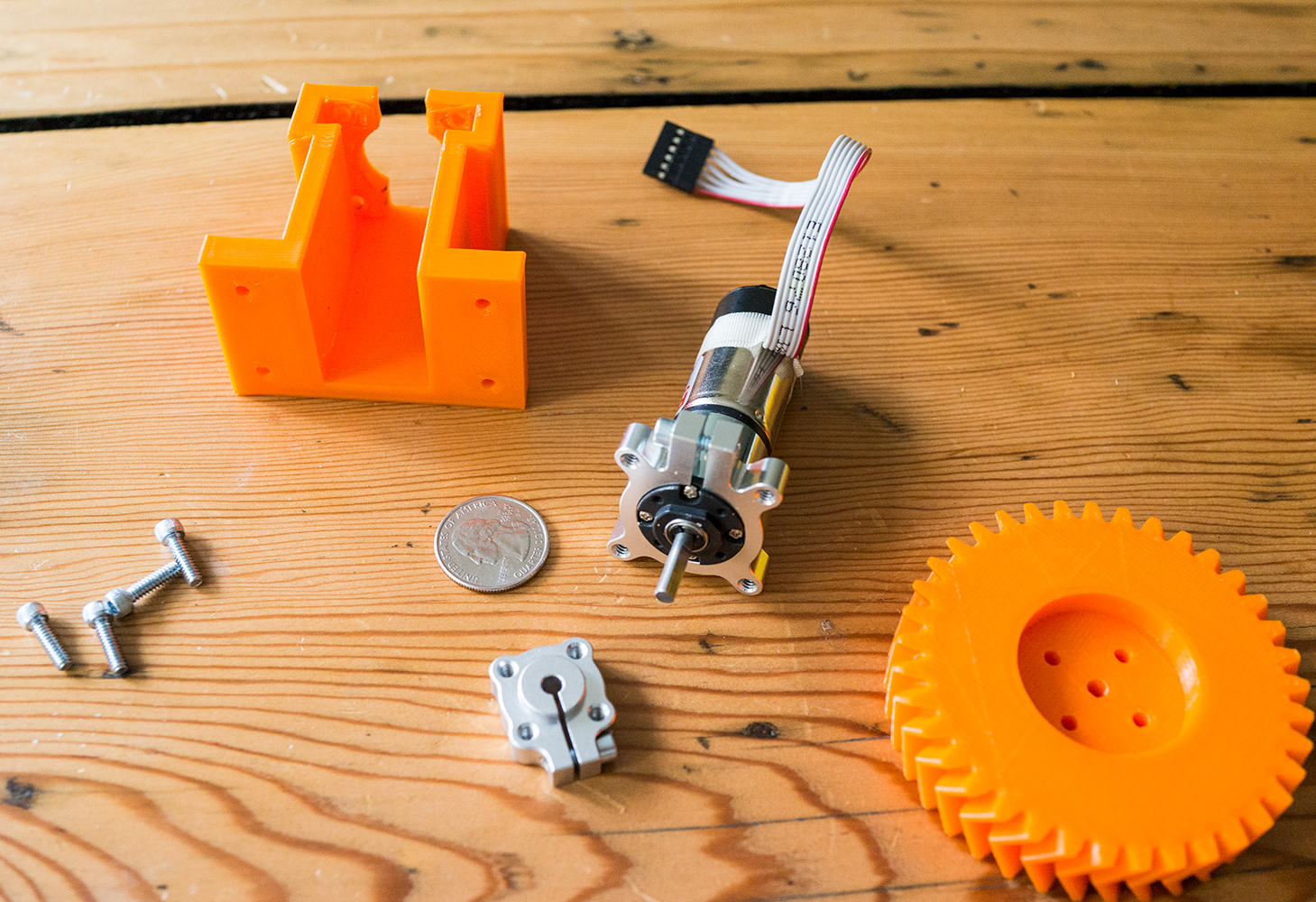
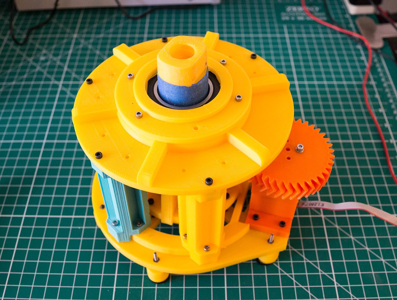
Frame
Everything is held in place by yet more plastic! I used a lot of struts to ensure that there will be no movement in the final frame. Additionally, I added little feet, 3D printed separately, with felt pads as this all this plastic has been scraping up my tables. I expect I will need to swap these feet out with something I can clamp down as the expected center of mass of the arm will easily be able to extend outside of this area.
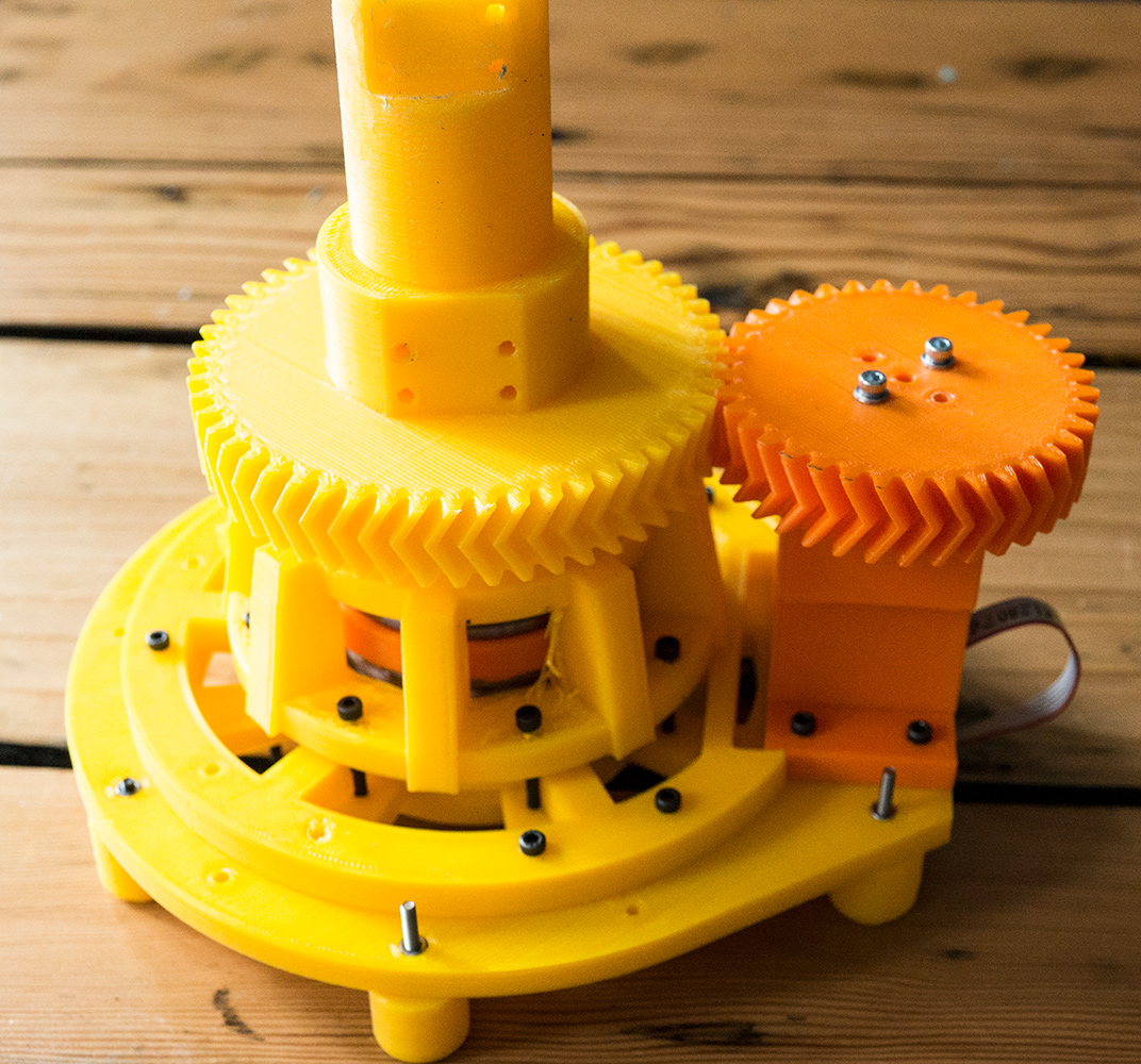
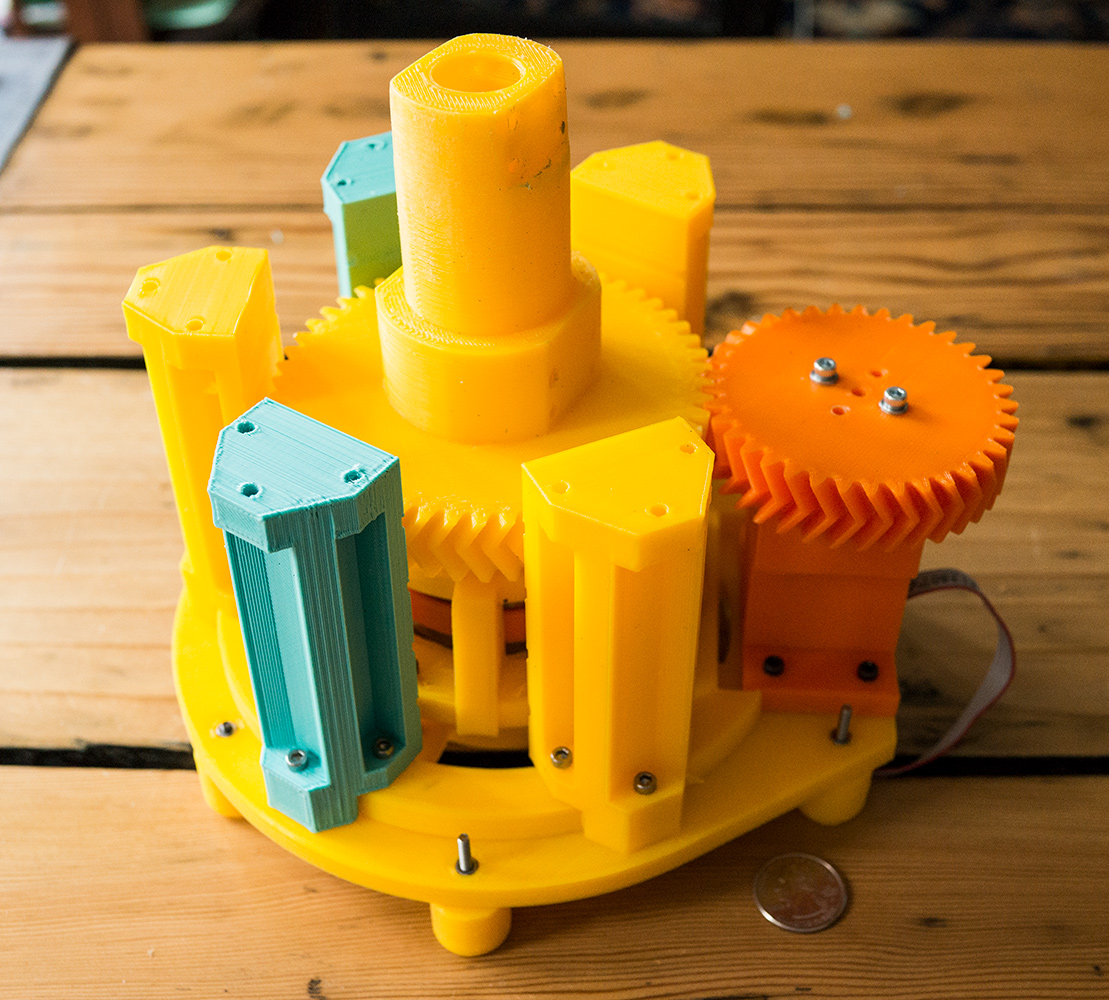
Result
Everything seems to work! The motor spins, the 3D printed shaft seems strong enough, and I can put a lot of weight on it. See the video for this thing in action! There is still a decent amount of friction, though. It’s not enough to be a problem (I hope), but I am curious as to the source. The thrust bearing should be beefy enough to hold a lot more weight than what I have tested. Worst case, I can upgrade the motor. In general, I think I went a bit overboard on the stability of the thing. The first design was a little wobbly, so I thickened the plastic pretty much everywhere. This is okay for the base and Axis 1, but as weights starts to matter, (Axis 2 and 3), I need to find a way to cut down on plastic.
Coming from a machine learning background, this type of design iteration, seems like something that I should not have to be doing by hand. I should probably invest time into learning a finite element analysis package and then manually making edits based on results. Taking this further, I wish things like topology optimization were more widely available in hobby grade products.
In general, it seems like it’s harder to express these 3D objects / designs in a transferable and modifiable way as is done in software. JSON, Images, and TensorFlow graphs, for example, are all data structures that lend themselves to reason. Parametric CAD models on the other hand are quite difficult, even FeatureScript. To make meaningful edits, I need at least the visual “compiled” part. Meanwhile, all this is implicitly tied to some notion of “functionality”: how this part is going to be used, what needs to be strong, and what the maximum size of the item is to make things fit together? This coupling reminds me some “modern” software libraries springing up that make this separation explicit. Things like TensorFlow, for example, separate graph construction from execution. Similarly, Halide, which does the same for algorithm design from the execution schedule. Even web frameworks such as Angular have some of this notion of separation of data and rendering! I am curious if any radically different workflow could be applied successfully to the mechanical design world.
Still so much to do! I am currently wrapping up the assembly and printing of the 2nd axis, and am thinking about designs for the 3rd and 4th. I am also wondering how the electronic system will function. The more I work on this project, the more I am amazed by the technology put into these commercial arms. It’s not as easy as it looks!